Valve Failure Analysis: A Root Cause Investigation Method
A structured method for investigating valve failures in the field — evidence collection, metallurgical analysis, common root causes, corrective actions and closing the loop.
Valve Failure Analysis: A Root Cause Investigation Method
When a valve fails, the pressure to restore production usually wins over the discipline to understand why. The failed trim gets replaced, the line restarts, and the same failure returns months later on the same valve or its neighbor. A root cause investigation breaks that cycle, but only if it is run as a method rather than as an improvised walk-around. The approach below is drawn from how failure analysts actually work when a valve arrives at a laboratory or when the investigation must happen in the plant.
Classifying the Failure First
Classification is not bureaucracy; it determines where to look. Most valve failures fall into a small set of categories, each with its own likely causes and its own required evidence.
- External or internal leakage — packing leaks, flange leaks, seat leakage. Look at the sealing system, the actuation of the closure member, and whether the valve was ever really tight.
- Operation seizure — the valve will not stroke or strokes with abnormal effort. Look for corrosion product in the bonnet, debris in the trim, galling on stem and guides, or deformation of the body from pipe stress.
- Fracture — of stem, disc, body, bolts. Fracture surfaces are the single most information-rich artifact, and they must be preserved intact.
- Erosion — accelerated metal loss at seats, plugs, or body walls near flow direction changes. Look upstream for particulate, cavitation, or droplet impingement.
- Corrosion — general or localized, including chloride pitting and stress corrosion cracking in austenitic stainless parts.
- Actuation failure — actuator, gearbox, or signal faults that present as "valve failure" but originate outside the pressure envelope.
Preserving Evidence at the Site
The first hours after a failure destroy more evidence than the failure itself, because plant routines take over: parts get tossed into scrap bins, surfaces get wiped, welders repair the adjacent pipe. Before anything is moved:
- Photograph the installation from multiple angles, including piping configuration, supports, orientation, and any visible damage or staining.
- Record the operating context: process conditions at the time, recent transients, upstream work, and the valve's identification against the datasheet.
- Keep fracture faces dry, clean, and protected. Do not fit the mating halves back together — doing so destroys the fracture topography that distinguishes fatigue from overload.
- Collect the failed pieces, plus comparator samples of the same material if available, and label every item with its location in the assembly.
- Note who handled what, so chain of custody is intact if the findings later enter a warranty or insurance discussion.
Laboratory Examination
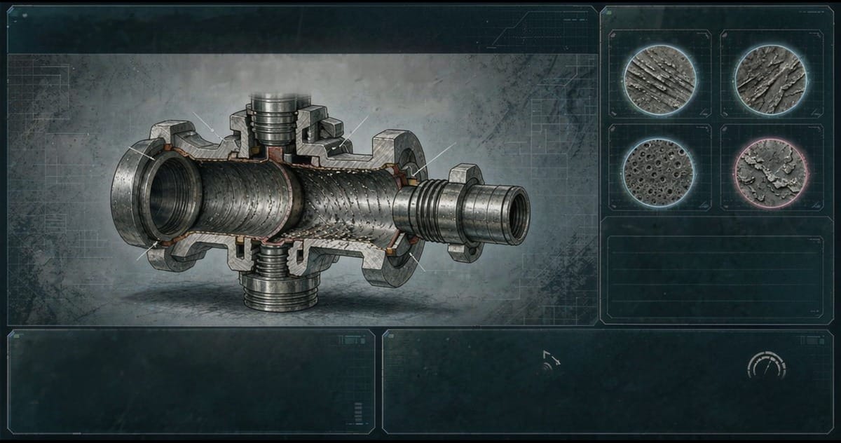
Where the failure justifies it, a metallurgical laboratory examination follows a standard sequence. Visual and low-magnification inspection of the fracture surface usually identifies the failure mode: beach marks and ratchet lines indicate fatigue, intergranular texture with staining suggests stress corrosion, and shear lips with macroscopic plastic deformation indicate overload. Scanning electron microscopy then confirms the mode at high magnification.
Metallographic sections through the crack origin reveal microstructure, decarburization, sensitization, or inclusions. Hardness surveys and tensile or chemical tests on the affected component verify whether the material matches the specified grade. On welded valves, a section through the weld can confirm whether a post-weld heat treatment was performed or skipped.
Two checks are routinely forgotten and frequently decisive: material verification against the certificate, and dimensional check of the trim against the drawing. Mis-marked bar stock and trim machined off drawing are not exotic — they recur in failure statistics across the industry.
Reconstructing the Duty
Hardware evidence only becomes a root cause when it is combined with the duty history. Pull the process data for the period before the failure: pressure and temperature records, cycling frequency, media composition, and any excursions. Interview the operators about events that never made it into the log — a water hammer after a fast valve closure, a steam-out at an unusual temperature, a bypass left open. Many "material failures" turn out to be misuse failures once the timeline is honest.
The Root Causes That Recur
Across industries, the same root causes account for most valve failures:
- Water hammer and pressure transients that exceed design loads and fracture bodies or collapse internals.
- Cavitation in liquid service across throttling valves that were sized or staged without a cavitation check.
- Installation stress — pipe misalignment forced onto flanges, inadequate support, thermal expansion fighting a rigid anchor — which distorts bodies and binds stems.
- Misapplication, such as a soft-seated valve on a service with abrasive particles, or a valve rated for one fluid used on another that attacks the seals.
- Material mix-up, where the delivered trim does not match the specified grade, often with a certificate that genuinely accompanies a different heat.
Choosing Corrective Actions at the Right Level
The corrective action must address the cause, not the symptom. A cracked body caused by water hammer is not fixed by a thicker replacement body; it is fixed by slowing the closure, adding surge protection, or re-sequencing the operation. A useful hierarchy:
- Eliminate the damaging condition at the source where possible — surge control, cavitation staging, filtration, pipe stress relief.
- Redesign the selection if the valve type or trim is wrong for the duty.
- Upgrade the material or trim specification where the duty is legitimately severe.
- Change the operating procedure and train where the cause is misuse.
- Replace like-for-like only when the investigation confirms the valve was right and its failure was an isolated quality escape.
Reporting and the Knowledge Base
An investigation that ends in a conversation ends nowhere. Write a structured report: the failure description, evidence, analysis, root cause, corrective actions, and the verification plan — how you will confirm the fix worked. Feed the findings into a searchable knowledge base keyed by valve type, service, and plant area, so the next specification engineer meets the lesson before the next failure instead of after it.
The management loop is what prevents recurrence. Audit whether corrective actions were actually implemented, review the failure database periodically for patterns, and requalify valves that were derated or restricted as a result. A plant that closes this loop stops buying the same failure twice.
Working with the Manufacturer
When the investigation needs material verification, metallurgical cross-sections, or a review of the original design basis, the valve manufacturer's engineering team is a necessary participant. They hold the drawings, the material certificates, and the manufacturing records needed to distinguish a design issue from a manufacturing escape from an installation issue.
An experienced manufacturer that produces the full valve range in-house — ball valves, control valves, gate valves, globe valves, check valves, strainers, knife gate valves, plug valves and butterfly valves — can support failure investigations with material records, laboratory examination, and engineering review of the replacement specification. Send the failure details and duty data to the manufacturer's applications team for a joint root cause review.