Pulsation and Valve Selection on Reciprocating Pump
How flow pulsation from reciprocating pumps fatigues check valves and isolation valves, and how to select, install and monitor valves for long service on discharge lines.
Pulsation and Valve Selection on Reciprocating Pump Discharge Lines
Reciprocating pumps are indispensable where high discharge pressure and accurate metering are required, but they impose a duty on the attached piping and valving that centrifugal pumps never do. The plunger or piston delivers flow in discrete strokes rather than as a steady stream, so every component downstream lives with a flow that rises and collapses several times per revolution. Valves on the discharge line are usually the first items to show the consequences: seats that hammer, stems that loosen, flanges that crack at the hub. Selecting valves for this service is less about pressure class alone and more about understanding what pulsation does mechanically over years of operation.
Why Reciprocating Pumps Pulsate
A single-piston pump delivers flow only during the discharge stroke and takes none during suction, producing the most severe pulsation profile. Multi-throw designs smooth the profile by overlapping strokes, but even a well-phased quintuplex pump leaves a residual flow ripple that translates directly into pressure ripple wherever the line contains liquid with limited compressibility.
The magnitude of the pressure pulsation depends on more than the pump. Line length between the pump and the first significant reflection point, liquid velocity, the presence of gas pockets, and the acoustic resonance of the piping span all amplify or damp what leaves the pump. This is why two identical pumps in different plants can behave very differently: the piping itself is part of the pulsation system.
What Pulsation Does to Valves
The failure mechanisms on a pulsating discharge line are well documented and repeat across plants and liquids.
- Check valve chatter. As instantaneous flow swings from high to near zero each stroke, a conventional swing check or dual-plate check never settles. The disc lifts and slams repeatedly, sometimes hundreds of times per minute, wearing the seat face and the hinge or spring far faster than the duty table predicts.
- Seat impact damage. Repeated seating at high closing velocity deforms soft seats, work-hardens metal seats, and eventually produces a leak path that no amount of downstream isolation can hide during a seat test.
- Stem and fastener fatigue. Pressure ripple transmits cyclic load into bolted joints, gland followers, and yoke connections. Stem threads and packing gland studs are common fatigue initiation points, particularly where support is poor.
- Fastener and flange loosening. Vibration walks nuts loose. A leaking flange on a pulsating line is rarely a gasket problem alone; it is usually a joint that was never designed against cyclic loading.
The important point is that these are cumulative mechanisms. A valve may pass the bench hydro test, install perfectly, and still fail in service within a modest operating period because the selection treated the discharge line as steady flow.
Dampeners and Pulsation Attenuators
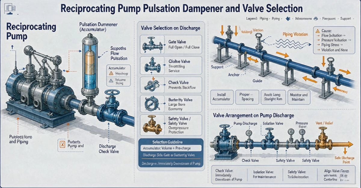
The first line of defense is not the valve at all but the pulsation dampener installed close to the pump discharge. A properly sized bladder or gas-cushioned dampener absorbs the flow ripple at its source, and every valve downstream benefits. Devices of this kind should be positioned as near the pump discharge flange as the layout allows; a dampener located far downstream, after a long spool piece, protects that spool piece and the reflection behavior but leaves the immediate valve group exposed.
Where the pump is supplied under an API 674 purchase specification, the pulsation study is normally part of the package. The study predicts pressure pulsation levels at each node of the piping system and identifies acoustic resonances. Valve selection should be reviewed against that study rather than against an idealized steady-flow assumption, because the study output tells you where the cyclic loads will actually concentrate.
Check Valve Selection: Favor Spring-Loaded Fast Closing
On a steady-flow line almost any check valve that fits the class rating will close and hold. On a pulsating line the ranking changes sharply.
- Spring-loaded axial or piston-type check valves are the preferred choice. The spring holds the closure member near the seat at low flow, so the disc does not swing freely, and the short travel with light spring return closes the valve before meaningful reverse flow develops. Seating velocity stays low even when the flow cycles constantly.
- Swing checks perform poorly. The long disc travel and heavy closure member mean the disc chatters through every pulsation cycle, and hinge wear eventually allows the disc to slam asymmetrically, damaging the seat and sometimes the body.
- Dual-plate checks close quickly but the plates flutter under sustained pulsation; torsion springs see high cycle counts and the plates can fatigue at the pivot.
Sizing matters as much as type. An oversized check valve operates near the seat crack point for much of the stroke cycle, which maximizes chatter. Select the check valve so its operating point sits comfortably open during peak instantaneous flow while the spring keeps it near-closed through the trough. This often means choosing a smaller check valve than the line size, which is entirely acceptable and frequently correct.
Isolation Valves on Discharge Lines
Gate and ball valves are common isolation choices, and both can serve well if a few pulsation-specific points are respected. Full-bore ball valves with metal or reinforced seats handle vibration well, but the seat loading must tolerate cyclic pressure without cold flow. Gate valves should be specified with robust gland arrangements; a flexible graphite packing set with a live-loaded gland follower resists the loosening that cyclic loading causes in a standard two-stud gland.
Avoid throttling with these valves. A gate valve left cracked open on a pulsating line sees flow-induced vibration across a partially open disc and will erode the seat within a short operating window. If regulation is needed, install a dedicated control or globe valve designed for the duty.
Installation Position and Piping Support
Valve placement on the discharge line should follow the pulsation study. Practical rules that hold in most layouts:
- Put the check valve as close to the pump discharge as practical, downstream of the dampener if one is fitted.
- Avoid hanging valve mass on unsupported spools near the pump; every valve and flange is a point mass, and pulsating lines have low natural frequencies that valve weight can pull into resonance.
- Support both sides of every flanged valve group, and use spring hangers where thermal movement exists.
- Anchor and guide the line so cyclic thrust from pressure ripple does not accumulate at the pump nozzle, which is a common cause of nozzle cracking and misalignment.
Maintenance and Monitoring
Valves on pulsating service reward routine attention. Torque trending on the valve handwheel or actuator is one of the most useful field indicators: a rising operating torque on a gate or globe valve signals packing consolidation, seat scoring, or debris in the trim long before external leakage appears. Log the torque at each stroke and act on the trend, not on the absolute value.
For check valves, periodic inspection of the seat and spring is warranted on critical services. Acoustic monitoring can reveal chatter that is not visible from the outside. Where a spring-loaded check has served through a long period of continuous cycling, treat the spring as a wear component and replace it at overhaul even if it looks intact, because fatigue in spring steel is not reliably detectable by eye.
A Selection Checklist for Pulsating Discharge Lines
- Confirm the pulsation study exists and read the predicted levels at each valve location.
- Specify spring-loaded fast-closing check valves; avoid swing checks on cyclic service.
- Size check valves for the instantaneous flow band, not the mean flow.
- Select isolation valves with vibration-resistant glands and live-loaded bolting where practical.
- Never use isolation valves for throttling on these lines.
- Place valves per the study, support both flanges, and respect pump nozzle load limits.
- Trend valve operating torque and inspect check internals on a defined cycle.
Bringing the Review Together
Reciprocating pump discharge lines are unforgiving of steady-flow assumptions, but they are entirely manageable with the right valve types, sensible placement, and disciplined monitoring. The failure patterns are known, and a selection review that accounts for cyclic loading costs little at the specification stage and prevents most of the field failures described above.
An experienced manufacturer that produces the full valve range in-house — ball valves, control valves, gate valves, globe valves, check valves, strainers, knife gate valves, plug valves and butterfly valves — can support this review with pulsation-aware selection advice, spring-loaded check valve data, and test documentation. Send your line conditions and pump data to the manufacturer's applications team for a per-line proposal.