Gearboxes and Manual Operators: Selecting Bevel, Spur
How bevel, spur, and worm gear manual operators differ in ratio, efficiency, and self-locking — plus torque, handwheel force, position indication, and ISO mounting guidance.
Gearboxes and Manual Operators: Selecting Bevel, Spur, and Worm Gear Units
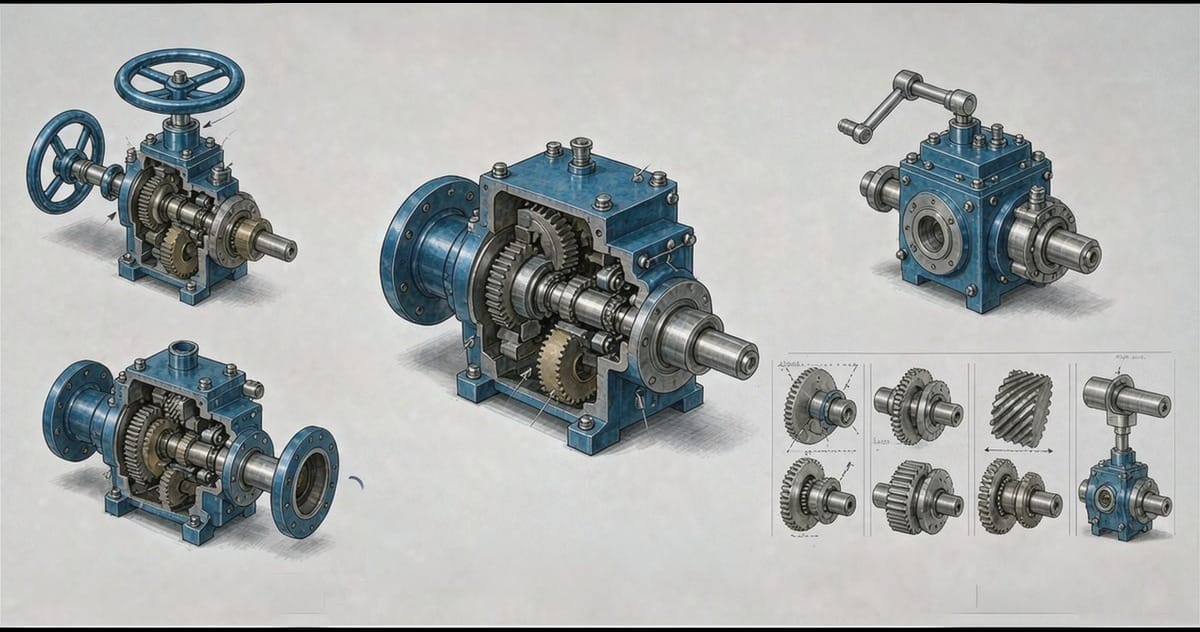
A manual gearbox is the least glamorous component in a valve package and one of the most frequently misapplied. The errors are consistent: a worm unit chosen where self-locking was assumed but not guaranteed, a handwheel force left off the datasheet until an operator cannot close the valve in an emergency, a gear unit bolted to a valve through mismatched mounting interfaces. None of these surface at the test bench — all of them surface in the field, usually at the worst possible moment. This article covers how the three principal gear types behave, what to specify around torque and handwheel force, and the interface standards that make the whole package match.
Why Gearboxes Exist on Valves
Large valves need more torque than a stem can usefully take from bare hands, and many need the operating position moved away from the valve itself — up out of a trench, over a walkway, or around an obstruction. A gear unit does both jobs: it multiplies input torque through a gear ratio, and many designs reorient the input so a handwheel sits where a person can stand.
The three common gear types solve the problem differently, and the differences are not interchangeable.
Worm Gear Units
The worm gearbox is the default for quarter-turn valves — ball, plug, and butterfly — and for larger multi-turn isolation duties. A screw-type worm drives a wheel whose shaft is typically the output, often at right angles to the input. The defining characteristics:
- High ratios in a single stage. A worm mesh delivers large speed reduction and torque multiplication in one compact stage, which is why a modest handwheel can seat a big ball valve.
- Partial self-locking by nature. The friction between worm and wheel resists back-driving, and in many designs the load genuinely cannot rotate the worm. But self-locking is a function of lead angle, friction coefficient, lubrication condition, and vibration — it degrades when a gearbox sits in a vibrating line, and it is never a substitute for a designed locking feature. If the valve must be positively locked, specify a locking device or a self-locking-verified design, and verify it.
- Lower efficiency. Worm meshes convert a meaningful share of input work to heat. That is the price of the ratio and the inherent anti-backdrive behavior, and it shows up directly as higher handwheel force for a given output torque.
- Handwheel axis perpendicular to the stem in the common arrangement, convenient for buried or elevated installations with extension stems.
Bevel Gear Units
Bevel gearboxes use meshed conical gears, typically at a right angle. Their defining feature is efficiency: a bevel mesh wastes far less power than a worm, so for the same output torque the handwheel force is noticeably lower. Where an operator must stroke a valve quickly and repeatedly — drain valves, furnace isolation, quick-closing duties — that efficiency difference is felt directly in the hands.
Bevel units, however, do not self-lock. Any position where the medium or spring force can back-drive the stem needs an external lock, a brake, or acceptance that the valve position is only held by stem friction. Bevel gearboxes are common on gate and globe valves and on multi-turn applications where speed matters, and they are the standard choice where the gearbox feeds an actuator mounting or where rapid manual operation is a design requirement.
Spur Gear Units
Spur gearboxes keep input and output on parallel axes. They are the simplest and most efficient of the three, used on multi-turn valves — gate, globe, and knife gate — where no change of direction is needed. Their strengths are mechanical efficiency, compactness, low cost, and easy maintenance; their limits are the modest ratio per stage and no inherent self-locking. For a gate valve on a clean water main, a spur unit is often the correct and most economical answer.
Torque, Handwheel Force, and the Safety Margin
The core sizing calculation is unglamorous but unforgiving. Total required torque is the valve's maximum operating torque — usually the seating or unseating value, whichever is higher — multiplied by service factors for pressure, media, and the differential the valve may see closed. The gearbox ratio then determines input torque, and handwheel force follows from input torque divided by the handwheel radius.
Two specification points are routinely missed:
- Maximum handwheel force is a design limit, not a target. Most operators can pull far harder on a wheel than standards assume; a gearbox sized so that emergency operation needs superhuman force is a gearbox sized wrong. State the maximum permissible handwheel force and size the unit so normal operation sits comfortably inside it.
- The differential-pressure assumption matters more than the valve's rated pressure. Sizing to rated pressure with zero differential is optimistic; the realistic case is the valve closed against full differential, and the gearbox should be selected for that.
Position Indication, Limits, and Protection
Manual operators carry responsibilities beyond torque:
- Positive position indication. The handwheel or pointer must show open and closed unambiguously. On quarter-turn units the pointer travels through the full quadrant; on multi-turn units a stroke counter or indicator plate prevents guessing.
- Adjustable stops. Travel stops at open and closed positions set on the gearbox protect the valve from overtravel, which on resilient-seated valves deforms seats and on metal-seated valves damages sealing surfaces.
- Over-torque protection. In manual service this is procedural rather than mechanical — operator training and marked handwheel force limits — but where gearboxes feed automated packages, the same limits become the actuator's torque settings. A seized valve must not be forced closed by a unit capable of destroying the stem.
- Locking provision. Where position must be positively held — sampling duties, safety isolation — a padlockable lock plate should be specified rather than relying on worm friction.
Lubrication and Environmental Protection
A gearbox is a lubricated machine sitting outdoors, and its maintenance profile should be considered at selection. Grease-lubricated units with sealed bearings suit most valve duties and reduce scheduled attention to periodic grease replenishment at the fittings provided. Gear cases should be verified for:
- Sealing integrity at the input and output shafts against dust and water ingress.
- Adequate ingress protection for the installed environment — a higher rating for washdown and coastal exposure than for a dry plant room.
- Corrosion protection of the housing and fasteners consistent with the atmosphere.
Buried and immersed installations deserve separate treatment. A gearbox in a valve chamber or below grade sees standing water, condensation, and flooded conditions that defeat ordinary enclosures; extended spindles and submersible-rated gear units with fully sealed housings exist for exactly these duties, and specifying ordinary IP protection there is a known way to convert a gearbox into a corrosion mass within a few seasons.
Matching Interfaces: ISO 5210 and ISO 5211
Interchangeability at the valve-gearbox and gearbox-accessory interfaces is standardized, and using the standards prevents most field-matching problems:
- ISO 5210 defines the flange and driving component dimensions for multi-turn valve actuators — the interface between a gearbox and a multi-turn valve, or between a gearbox and an electric multi-turn actuator.
- ISO 5211 defines the flange and star-drive dimensions for part-turn (quarter-turn) actuators — the interface between a gearbox and a ball, plug, or butterfly valve.
Specifying the standardized interface size for each valve means gearboxes, actuators, and mounting brackets remain interchangeable across brands and across decades of spares — a small discipline in the datasheet that pays off for the life of the plant.
Common Selection Errors
The recurring failures are few and preventable:
- Assuming worm gearboxes self-lock in every condition, without verifying the design or providing an external lock.
- Leaving maximum handwheel force unspecified and discovering at commissioning that seating a valve against full differential needs two people.
- Selecting the gearbox torque from rated pressure rather than the realistic closed-valve differential.
- Installing standard protection-class units in buried or submerged chambers.
- Mixing non-standard mounting interfaces and losing the ability to swap actuators or gear units later.
An experienced manufacturer that produces the full valve range in-house — ball valves, control valves, gate valves, globe valves, check valves, strainers, knife gate valves, plug valves and butterfly valves — can support this review with torque data, handwheel-force calculations, and standardized mounting options for each valve series. Send your Valve Schedule or the key parameters for each position to the manufacturer's applications team for a per-line proposal.