Fail Open, Fail Closed, or Fail Last: Defining Safe
How to define the required failure position for automated valves — fail open, fail closed, or fail last — with spring-return, accumulator, and ESD design guidance.
Fail Open, Fail Closed, or Fail Last: Defining Safe Positions
Few specification errors cause as much rework as getting the failure position wrong. The valve does not care; the actuator simply does what its design dictates when power disappears. But a fuel-gas valve that fails open where the safety case assumed fail closed — or the reverse on a furnace feed — is a change order touching the actuator, the solenoid scheme, the air supply design, the logic, and the shutdown analysis. The failure position is a process safety decision made line by line in the design phase, deliberately rather than inherited from the previous project's datasheet.
What the Terms Actually Mean
The failure position describes where the valve goes when its external power sources are lost. Three positions are defined, and the interesting part is what each one assumes about the loss.
- Fail Closed (FC). On loss of actuating power, the valve moves to the closed position. Used where flow must stop on failure — fuel gas, flare protection, pump discharge isolation, any duty where uncontrolled continued flow is the hazard.
- Fail Open (FO). On loss of power, the valve moves to open. Used where stopping the flow creates the hazard — cooling water to a reactor, quench flows, vent lines, lube oil feeds. The classic mistake on FO valves is to treat them casually because they are "safety" valves; they deserve the same rigor, since a spurious closure can be as damaging as a spurious opening on an FC line.
- Fail Last (FL), also Fail in Place or Fail Lock. On loss of power, the valve holds its last position. Used where movement itself is the hazard — where slamming a large valve shut could cause surge pressure, or where the current position is the safest one for the transient.
A subtlety worth stating in the specification: failure of what? Air, electricity, and signal can be lost independently, and many real events are partial — signal lost but air available, power lost but the logic solver alive. Define the response for each combination, not just for total loss.
How Each Failure Position Is Achieved
The mechanism behind the position is the actuator's power architecture, and it drives cost, complexity, and reliability in different directions.
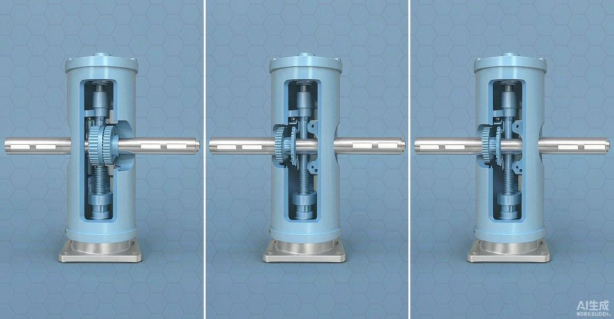
- Spring-return actuators (single-acting). The actuating medium — typically instrument air — works against a spring in one direction only. When air is vented, the spring drives the valve to its failed position. This is the simplest and most dependable way to get FC or FO: no stored energy beyond the spring, no logic required. The trade-offs are a larger, heavier actuator for the same torque (the spring consumes stroke), and a full-force motion to the failed position on every vent event, which brings its own transient issues on large valves.
- Double-acting cylinders with accumulators. For large quarter-turn or linear valves where a spring package would be impractically big, a double-acting actuator with a stored-air or hydraulic accumulator can drive the valve to the safe position on power loss. It behaves like spring-return but the "spring" is a pressure vessel, so it needs its own maintenance and integrity monitoring — an accumulator that has quietly leaked down over the years converts a fail-closed design into a fail-last one, discovered only when tested.
- Fail-last implementations. True fail-lock can be achieved mechanically with pilot-operated locking valves that trap air in the actuator chambers on signal loss, or with hydraulic systems that hold position by check valves. Note the difference between designed fail-lock and incidental fail-lock: a double-acting actuator with no accumulator and no lock circuit will simply drift or stay wherever friction leaves it — which is not a defined position and should not be sold to the safety case as fail-last.
- Electric actuators. These consume power to move, so their inherent behavior on total power loss is fail-last. Fail open or fail closed requires either a spring attachment, a battery backup with defined ride-through duration, or a capacitor-based backup system. Backup power changes the question from "what position" to "how long" — the specification must state how long the actuator must hold the ability to move after power loss.
The HAZOP Connection
The failure position is not a mechanical preference; it is an output of the process hazard analysis. The HAZOP or equivalent review examines each control and isolation valve's role in credible dev scenarios and concludes, for each, which position minimizes risk on failure. The logic runs in both directions:
- An FC valve that slams shut can create its own hazard — water hammer, thermal relief demand downstream, deadheading a pump. Some lines need a controlled closure rate rather than a fast spring stroke.
- An FL choice must survive scrutiny: "hold last position" is only safe if every position the valve can be in is tolerable during the associated transient. That is a stronger claim than it sounds.
The specification should carry the HAZOP conclusion into the datasheet explicitly — position, plus the assumed cause of failure, plus any closure-speed requirement. When those three items are stated, the actuator design follows almost mechanically.
Partial Failure and Stuck-Valve Risk
Between "works" and "fails to safe" lies the uncomfortable middle: the valve that moves partway and stops. A spring-return actuator with a seized stem, a sheared stem, or debris in the seat may travel a fraction of its stroke and stall. For ESD duty this matters enormously, because partial closure may deliver neither isolation nor full flow. Safety integrity analysis for shutdown valves considers partial-stroke behavior, which is one reason partial-stroke testing of ESD valves has become standard practice — it both verifies the valve can move and, on some architectures, reveals stall conditions without shutting the process down.
The specification responses:
- Define the valve's safety role precisely: isolation for maintenance (where stuck is an inconvenience) or emergency shutdown (where stuck is an incident).
- For ESD duty, require proof-test capability and consider partial-stroke test provisions in the logic and the solenoid scheme.
- Consider what the downstream protection does when the valve fails mid-stroke — relief sizing and surge analysis should assume it.
ESD Valves Versus Control Valves
The failure-position discussion applies differently to these two populations. A control valve's failure position is about the loop: with the signal lost, should the loop's final element go closed, open, or hold? Positioners and relay logic make this configurable with modest cost. An ESD isolation valve's failure position is about the safety instrumented function: the response to a shutdown demand or a total energy loss, verified by proof testing and analyzed for availability. Conflating the two — assuming the control valve's FC characteristic covers the isolation requirement, or vice versa — is a recurring audit finding. They are different requirements with different verification regimes, even when the same physical valve serves both.
The Confirmation Checklist
Before releasing the datasheet, walk this list with the process engineer for each automated valve:
- What is the hazard if flow continues on failure? If real, FC is likely.
- What is the hazard if flow stops? If real, FO or FL is likely.
- Is every possible held position tolerable, if FL is chosen?
- What exactly fails: air, electric, signal — and what should the valve do for each loss individually?
- Is the closure speed on failure acceptable, or is damping needed?
- Is the required failed position achievable without a spring, and if via accumulator or battery, who maintains that stored energy and how is it proven?
- Does the safety case treat this valve as isolation or as part of the SIF, and does the test regime match?
Getting these answers onto the datasheet costs an afternoon; discovering a wrong failure position during commissioning costs the actuator, the schedule, and often the air supply design. For complex requirements — dual failure modes, limited spring space, hybrid air-over-oil schemes — early dialogue with the actuator and valve designer pays for itself.
Getting the Definitions Right at the Source
State the failure position, the failure cause scenarios, and the closure-speed requirement on every automated valve line in the schedule, and hold the design review against it. An experienced manufacturer that produces the full valve range in-house — ball valves, control valves, gate valves, globe valves, check valves, strainers, knife gate valves, plug valves and butterfly valves — can support this review with actuator sizing, spring-return and accumulator configurations, and test documentation. Send your Valve Schedule or the key parameters for each position to the manufacturer's applications team for a per-line proposal.