Choked Flow in Control Valves: When Sizing Equations
Why control valve sizing equations fail at choked flow, how liquid and gas choking are detected with FL and xT factors, and the design responses when a valve chokes.
Choked Flow in Control Valves: When Sizing Equations Break Down
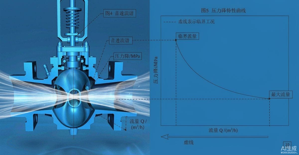
The standard valve sizing equation carries a hidden assumption: that flow through the valve increases smoothly with the square root of the pressure drop. Increase the drop, get more flow — indefinitely. That assumption fails in real valves. Past a certain pressure drop, flow stops responding no matter how much additional differential is applied: the flow is choked. Specifiers who ignore choking do not merely get a slightly wrong Cv — they get valves that are undersized in fact, noisy in operation, and destructive to themselves and their pipework.
What Choking Actually Is
Choking is a physical limit inside the valve, not a property of the equation. In a liquid valve, the flow accelerates through the trim, and by the Bernoulli relationship the static pressure at the narrowest point — the vena contracta — falls below the downstream pressure. When that local pressure reaches the liquid's vapor pressure at operating temperature, vapor forms. The flow stream becomes a two-phase mixture in the constriction, and further increases in upstream pressure or downstream pull no longer translate into more mass flow: the vapor voids block the passage.
In a gas valve, the mechanism is compressibility. As the pressure ratio across the constriction deepens, the gas accelerates toward sonic velocity at the throat. Once the local velocity reaches acoustic speed, pressure signals can no longer propagate upstream to accelerate the flow further — the flow is limited by the throat conditions alone, and additional differential buys noise rather than flow.
In both cases the practical signature is the same: a valve that refuses to pass more flow despite ample available differential.
Liquid Choking: Vapor Pressure and the Recovery Factor
For liquids, whether a valve chokes depends on the contest between the pressure drop and the liquid's margin above vapor pressure. The critical pressure drop — the drop beyond which flow no longer increases — is not a fixed fraction of upstream pressure. It depends on how much pressure the valve recovers downstream of the constriction, and that is where the valve's pressure-recovery factor (FL) enters the sizing math.
Two valves with identical Cv can behave completely differently at high drop:
- A low-recovery valve (globe trim with tortuous passages) dissipates a large share of the drop inside the trim, so the local pressure at the vena contracta stays comparatively high relative to the downstream pressure. It chokes at a higher available drop and, crucially, resists cavitation longer.
- A high-recovery valve (efficient ball or butterfly geometry) recovers much of the drop, which is efficient at moderate conditions but means the local pressure dips much further below the eventual downstream pressure. It chokes sooner and flashes harder when it does.
The sizing consequence: the maximum usable differential across the valve is a function of the upstream pressure, the vapor pressure at operating temperature, and the valve's FL. Any calculation that applies a drop larger than this critical differential to the standard liquid equation is over-predicting flow — sometimes grossly — and, just as importantly, predicting a valve that will cavitate violently.
Gas Choking: Critical Pressure Ratio and xT
For gases and vapors, the controlling quantity is the pressure-drop ratio — the differential divided by the absolute upstream pressure. The standard compressible flow equation holds only while this ratio stays below a limit; beyond it, flow is choked at the sonic condition.
The limit is not the textbook sonic threshold, because real valves are not ideal nozzles: the flow path through a cage or around a plug is tortuous, and the effective sonic condition arrives at a modified ratio captured by the valve's xT factor (adjusted further by the pressure-drop ratio factor at the actual operating conditions). The discipline is the same as for liquids: compute the pressure-drop ratio, compare it against the valve-specific limit, and if choking applies, switch to the choked-flow form of the equation with the appropriate factors. Applying the subcritical equation beyond the choke point will report a flow the valve cannot deliver.
Why Choked Operation Is a Design Problem, Not Just a Scheduling Problem
A valve operating choked is operating at its most abusive condition:
- Noise. Choked gas flow radiates intense aerodynamic noise — the shock structures downstream of the sonic region are efficient sound generators, and choked liquid flow adds cavitation noise on top. Noise predictions made for subcritical operation are meaningless when the valve is choked; the choked condition must be the input to the noise calculation.
- Vibration and fatigue. The unsteady flow structures associated with choking shake the trim, the actuator bracketry, and adjacent small-bore piping. Fatigue failures of tubing and instrumentation connections downstream of choked valves are a recurring field incident.
- Erosion and cavitation. For liquids, choking coincides with flashing and often cavitation; for wet or particulate-laden gases, sonic velocities accelerate erosion dramatically.
Multiphase and Dense-Phase Complications
Real processes complicate the clean picture. Flashing liquid upstream of the valve means the "liquid" sizing basis is already invalid — the fluid is two-phase before it reaches the trim. Gas with entrained liquid, flashing hydrocarbons across long drop spans, and supercritical fluids near their critical point all defy the single-phase equations to varying degrees. Standardized corrections exist for some of these conditions, but the honest engineering position is that multiphase valve sizing is approximation territory: it demands conservative margins, robust trim, and, where the service is economically significant, consultation with manufacturers who have test data on similar services.
The Correct Calculation Sequence
The failure mode in practice is not ignorance of the equations but skipping the check. The sequence that avoids it:
- Establish the actual operating conditions — not design conditions only, but the range, because a valve that is subcritical at design flow may be choked at a low-flow, high-dp corner of its operating envelope.
- For liquids: compute the critical pressure drop from upstream pressure, vapor pressure, and FL, and compare against the actual available drop. If the actual drop exceeds it, the valve is choked (and likely cavitating) — solve the choked case and evaluate the cavitation regime separately.
- For gases: compute the pressure-drop ratio against the xT-based limit; if choked, apply the choked-flow equation.
- Recalculate required Cv under the choked regime and confirm the selected valve passes the required flow.
- Run the noise prediction using the choked-flow result, and evaluate cavitation for liquids regardless of the choke verdict — a valve can cavitate damagingly at drops below the choke limit.
Design Responses When a Valve Chokes
Discovering that a position chokes opens several responses, in rough order of preference:
- Share the drop. Move part of the total drop to a static restriction — orifice plates or a restrictor — so the valve operates in its subcritical region. This is often the cheapest fix on stable services.
- Choose low-recovery trim. Multi-stage cages, drilled-hole trims, and labyrinth stacks consume the drop inside the trim in portions, raising the effective choke limit and taming cavitation and noise together.
- Change valve type. A high-recovery valve that chokes may be replaced by a globe with the same Cv that does not; conversely, a valve selected mainly for choked operation should not be a high-recovery design at all.
- Split the duty. Two valves in series, or a stage-valve plus trim-valve arrangement, halve the severity at each position.
None of these responses is visible to a sizing routine that never checks for choking in the first place. The check costs a minute; the field consequences of skipping it are measured in years of noise complaints and trim replacements.
An experienced manufacturer that produces the full valve range in-house — ball valves, control valves, gate valves, globe valves, check valves, strainers, knife gate valves, plug valves and butterfly valves — can support this review with choked-flow calculations, pressure-recovery data, and low-recovery trim options for each severe-duty position. Send your Valve Schedule or the operating pressures and flow conditions for each high-differential line to the manufacturer's applications team for a per-line proposal.