Butterfly Valve Body Styles: Wafer, Lug, and Double
Wafer, lug, and double flange butterfly valves differ in installation, isolation capability, cost, and maintenance. A practical comparison for pipeline engineers.
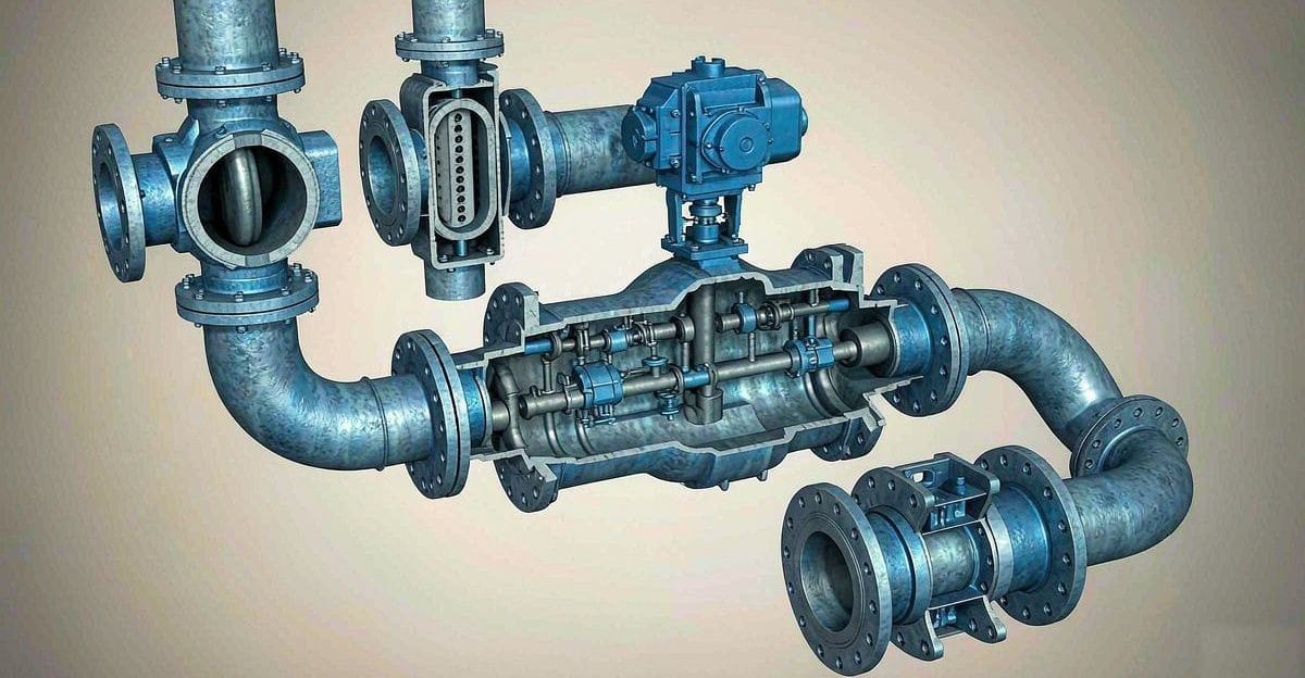
Butterfly Valve Body Styles: Wafer, Lug, and Double Flange Compared
Pick up any butterfly valve catalogue and you will find the same disc-and-seat technology offered in three distinct body styles: wafer, lug, and double flange. The sealing principle does not change between them. What changes is how the valve attaches to the pipeline, and that single difference drives installation cost, maintenance strategy, and even whether the valve can be used for a given duty at all. Choosing the wrong style is one of the more common and expensive mistakes in valve specification, because the consequences only show up years later, when someone tries to remove the valve without draining the line.
The Three Body Geometries
Wafer Body
The wafer body is the simplest and lightest of the styles. The valve is a thin sandwich element with no integral flanges; it is clamped between two pipe flanges by long through-bolts that pass completely across the valve body. Centering is usually handled by locating tabs or a raised boss on the body that fits inside the bolt circle of the mating flanges.
Because the body carries no flange drilling, a wafer valve is short-faced, compact, and inexpensive. The trade-off is that the valve is never self-supporting: if you unbolt one side while the line is under any load, the valve simply hangs on the bolts of the opposite flange, and removing it entirely requires breaking the line at both ends or dismantling a spool piece.
Lug Body
The lug body adds a ring of threaded lugs — blind tapped bosses around the periphery of the body. Bolts thread into these lugs from each pipe flange independently, so each side of the line connects to the valve with its own set of studs. This is the key structural difference, and it produces the lug valve's defining capability: the downstream side can be unbolted and the pipe blanked off while the upstream side remains connected and pressurized. In other words, a lug body supports one-sided line isolation, which makes it the standard choice where equipment downstream — a pump, a strainer, a section of plant — must be serviced without shutting down the whole system.
The lugs also let the valve act as an end-of-line valve when paired with a blind flange. A wafer valve cannot do this in most designs; clamped only from one side, the disc and seat assembly is not engineered to hold full line pressure against a single flange. Some high-performance wafer designs are rated for end-of-line service, but this must be stated explicitly by the manufacturer — it is never a safe assumption.
Double Flange Body
The double flange body carries full raised-face flanges, drilled and integral to the casting, on both ends. Connection is by conventional bolted flanged joints, one per side, exactly as with a gate or globe valve. This is the heaviest and most expensive style, but it is also the most mechanically independent: the valve is a self-supporting unit, the bolting loads do not pass through the body, and the joint behaves like any other flanged connection in the plant.
Double flange construction is the traditional choice for large diameters, for ductile iron and steel bodies in higher pressure classes, and for buried or underground service where joint rigidity and thrust resistance matter. Many specifications for water transmission simply require double flange below ground, full stop.
Installation and Removal in Practice
The maintenance story is where these styles separate most sharply.
- Wafer: fastest and cheapest to install initially, since only a single bolt set spans the assembly. But removal requires full line isolation on both sides and depressurization.
- Lug: allows downstream pipework to be dropped while the upstream side stays live, provided the valve itself is designed for that duty and the seat can seal against upstream pressure. Always confirm dead-end service capability in writing, because lug bodies in resilient-seat designs vary in what they can hold one-sided.
- Double flange: each joint is broken independently, exactly like any flanged valve. Heavier bolting work, but no surprises, and standard flange gaskets and procedures apply.
One practical warning applies to all styles: butterfly discs swing into the bore when open. The mating flanges must be the flat-face or recessed type specified by the maker, and nearby check valves or other bore-intruding equipment must be spaced far enough downstream that the disc never strikes them. This clearance error is far more common than body-style errors, and it damages the seat on the very first stroke.
Cost, Weight, and Pressure Range
Wafer bodies win on all three counts of cost, face-to-face length, and weight — sometimes dramatically at larger sizes, where the flange drilling of a double flange body adds substantial mass. For a plant full of low-pressure utility lines, the wafer style is usually the rational default.
Lug bodies cost more than wafer because of the machining of the tapped lugs, and they are typically offered in the mid diameter range. At the top of the size range the lug machining volume grows quickly, which is one reason lug bodies become less common on large water mains.
Double flange bodies sit at the top of the cost ladder, and they dominate where pressure classes rise — in steel-bodied, high-performance, and triple-offset designs the flanged body is standard, because the higher bolting loads and the mechanical independence of the joint justify the extra metal.
As a broad pattern: resilient-seated wafer and lug styles cover the low-to-mid pressure classes and the utility and water duties; high-performance and metal-seated designs in wafer, lug, or double flange extend into process pressures and temperatures; double flange is the default for large-diameter transmission and underground work. Exact limits depend on seat material and body material, so treat the pressure-temperature table for the specific design, not the style in general, as the governing document.
Blind Service and One-Sided Duty
The ability to hold pressure against one open side — "dead-end" or blind service — deserves its own emphasis, because it is a property of the body style plus the seat design, not of the valve type in general.
- A wafer valve clamped between two flanges is fine for line isolation but is generally not rated for end-of-line duty unless the manufacturer says so.
- A lug valve is the natural blind-service candidate; the threaded lugs take the one-sided load.
- A double flange valve with a blind flange on one side is fully rated, since the joint is conventional.
If your scheme depends on isolating a branch for maintenance while the main stays live, this requirement should appear in the specification explicitly, and the manufacturer's end-of-line rating — which is usually lower than the bidirectional in-line rating — should be checked at the design pressure of the live side.
Common Misapplications
The recurring mistakes seen in the field are predictable:
- Wafer used where one-sided isolation is needed. The downstream side cannot be dropped without a full shutdown, and retrofitting a lug valve later costs far more than specifying it initially.
- Assuming any lug valve is dead-end rated. The body style permits it; the seat design determines whether it is approved. Resilient seats in particular have pressure limits in blind service that are below their in-line rating.
- Underestimating wafer face-to-face dimension deviations. Mixing wafer valves from different design series in the same plant means the spool lengths do not interchange — a maintenance-stores nuisance worth avoiding by standardizing the dimension series early.
- Ignoring disc-to-flange interference with profile or tapered-hub flanges, and with adjacent check valves.
- Specifying double flange everywhere "to be safe." The weight and cost penalty across a plant full of small utility valves is real money spent on capability nobody uses.
Making the Choice
A sensible selection sequence runs: first decide whether one-sided isolation or blind service is required — that forces lug or double flange. Then check size and pressure class — large or high-pressure duties push toward double flange flanged-steel construction. Then weigh installation and future removal convenience against initial cost for the remaining positions, and standardize the wafer dimension series plant-wide before anyone orders.
Because body style interacts with seat material, disc design, and pressure class, it is worth reviewing the full valve schedule with the applications team of an experienced manufacturer that produces the complete valve range in-house — ball, control, gate, globe, check, strainer, knife gate, plug, and butterfly valves. The manufacturer's applications team can confirm end-of-line ratings for each position and return a per-line proposal with the appropriate body style, seat, and material documentation for each service.