Anti-Static Design in Soft-Seated Valves
Why soft-seated ball valves need anti-static paths, how spring-loaded seats and conductive gaskets work, and what API 6D resistance testing requires.
Anti-Static Design in Soft-Seated Valves
A soft-seated ball valve is, electrically speaking, a small insulating sandwich. The polymer seat rings that give the valve its tight shutoff also isolate the ball from the body, and the stem seals isolate the stem from the ball. In hydrocarbon service that combination is not just an inconvenience — it is a potential ignition source. Anti-static design exists to break those insulating barriers with deliberate, testable conductive paths, and it is one of those features that costs almost nothing to include and a great deal to leave out.
How Static Builds Up in a Valve
Static electricity in pipelines comes from the relative movement of dissimilar materials. Every time a fluid slides across a surface, charge transfers at the interface. The relevant mechanisms inside a valve are well understood:
- Fluid friction. Flowing hydrocarbons — especially refined, low-conductivity products like gasoline, jet fuel, and dry solvents — generate charge as they sweep past pipe walls, seat faces, and the ball surface. Higher velocity and higher turbulence mean more charge generation.
- Two-phase and multiphase effects. Bubbles, droplets, and entrained particles dramatically increase charge separation. A line that is benign on single-phase liquid can charge heavily during pigging, draining, or sprays.
- Mechanical operation. Rotating the ball against polymer seats, and the stem against its PTFE packing, rubs insulator against metal — a classic triboelectric pairing.
In a metal valve, all of this charge drains harmlessly to the body and through the piping to ground. In a soft-seated valve, the seats and seals interrupt that path. The ball can sit inside the body as an isolated conductor, holding charge like a small capacitor. The stem can be at a different potential than the body, with only a thin polymer seal between them.
The Ignition Risk
The hazard is a spark discharge. An isolated, charged component inside a vessel or valve can discharge across a gap when a nearby conductive object or operator provides the path. The ignition energies of common hydrocarbon vapors are tiny — well within what a human-body static spark produces — so even a modest charge accumulation is a genuine threat when the vapor space contains a flammable mixture.
The risk is sharpest in exactly the situations that are easy to overlook: a valve opened slowly during tank draining, vapor spaces above low liquid levels, initial fill after maintenance, and any operation where high velocity coincides with a two-phase mixture. Safety guidance for handling flammable liquids has long recognized static as a primary ignition source alongside hot work and electrical equipment.
The Anti-Static Construction
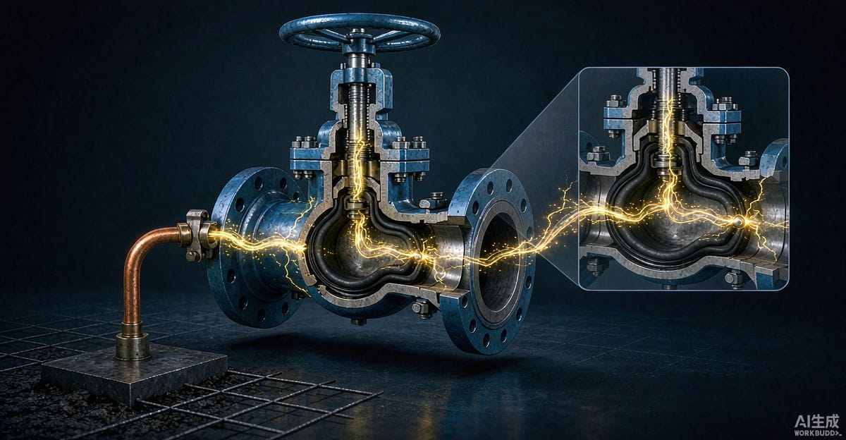
The accepted remedy is simple and robust: provide redundant metallic paths so that ball, stem, and body are always at the same potential, regardless of the insulating seats and seals.
- Spring-loaded seat-to-ball contact. The most common solution places small stainless springs behind each seat ring. The springs push a metallic plunger or the seat's metal backup ring against the ball surface, so the ball is connected to the body through the seat assembly on either side. The contact area is small but continuous, which is all that matters for static drainage.
- Conductive stem seals. Where the stem must remain isolated from the ball by polymer seals, a conductive washer, spring, or anti-static gland component provides a stem-to-body path. In some designs the stem is machined to contact a metal thrust collar directly.
- Conductive gaskets and spacers. Any polymer gasket in the body joints can be bridged with a metallic spacer ring, so the body splitline does not become an insulating joint.
- Redundancy. Good practice duplicates the paths. If the seat springs on one side fail or foul, the opposite seat still provides drainage. A single path through one spring is a single point of failure in a safety function.
A practical note on materials: the springs and contact elements should be selected for the environment. In wet or sour service, corrosion at the spring contact can quietly break the path while everything looks intact from the outside — a failure mode addressed below.
Resistance Requirements and Testing
Anti-static capability is defined numerically, not by intent. The relevant pipeline valve standard requires that the electrical resistance between ball/stem and body not exceed a stated maximum — the commonly applied figure being on the order of ten ohms — with a minimum requirement as well, so the path is conductive but not a stray-current bypass. Designers should verify the exact requirement in the edition of the standard governing their project, but the principle is universal: the paths must be demonstrably present, not merely shown on a drawing.
The test itself is straightforward, which is why it belongs on the routine test list rather than only in type testing:
- Method. A low-voltage resistance measurement is taken between the stem (or ball, where accessible) and the body. Dedicated micro-ohmmeters or standard multimeters are both used, depending on the specified accuracy.
- Acceptance. The measured value must fall within the specified band. A reading of infinite resistance means a spring is missing, deformed, or not contacting; a marginal reading usually points to contamination or a light contact.
- When to test. At minimum during production testing before shipment. For critical or corrosive service, specifying resistance verification at every valve, rather than by sampling, is a reasonable and inexpensive requirement.
Failure Modes in Service
The uncomfortable truth about anti-static paths is that they fail silently. Nothing in the process signals that a seat spring has corroded away or that a conductive washer has been left out during a repair. The valve continues to seal perfectly, and the safety function is gone while the function everyone watches — shutoff — remains.
- Corrosion at contacts. Rust or sulfide films at the spring-to-ball interface increase resistance by orders of magnitude. This is the dominant long-term failure mode in the field.
- Maintenance errors. Rebuilt valves are the highest-risk population. Springs that are lost, substituted with the wrong size, or simply forgotten during seat reassembly restore the insulating sandwich the design was meant to eliminate.
- Wear and debris. Particles embedded in the seat face can interrupt the metal-to-metal contact the springs rely on.
The consequences for plant practice: include resistance measurement in turnaround inspections for valves in flammable service, and treat anti-static components as controlled spares during any rebuild.
Procurement and Acceptance Clauses
For buyers, the specification work is short but should be explicit:
- State that anti-static paths between ball, stem, and body are required, with the resistance limit and the governing standard.
- Require resistance test results for the delivered valves, reported per serial number where the service is critical.
- Ask for the spring and contact materials, with justification for corrosive service.
- For valves expected to be rebuilt in the field, request assembly documentation showing anti-static component identification, so shop personnel know what must go back in.
Verifying the Design Before Order
The feature is inexpensive; the ambiguity is what costs money. Make the requirement contractual rather than assumed, and verify it in the test program rather than trusting the catalog description. An experienced manufacturer that produces the full valve range in-house — ball valves, control valves, gate valves, globe valves, check valves, strainers, knife gate valves, plug valves and butterfly valves — can support this review with test reports and material documentation for its anti-static constructions. Send your Valve Schedule or the key parameters for each position to the manufacturer's applications team for a per-line proposal.