Anti-Cavitation Trim: Multi-Stage and Stacked Disc Designs
How multi-stage, stacked disc, labyrinth and drilled-hole trim breaks pressure drop into stages to prevent cavitation and noise, and when simpler alternatives suffice.
Anti-Cavitation Trim: Multi-Stage and Stacked Disc Designs
Cavitation damage in a control valve is easy to recognize and expensive to ignore: metal surfaces downstream of the seat look like they were sandblasted, bodies erode through in months rather than years, and the pipework rattles with a noise like gravel in the line. The root cause is simple physics — the pressure drop was taken in a single step, at a rate the liquid could not absorb without flashing and collapsing vapor bubbles against solid metal. Anti-cavitation trim exists to defeat that mechanism, and the design families now available — multi-stage cages, stacked discs, labyrinths — deserve to be understood as engineering choices, not catalog options.
Why Single-Stage Trim Cavitates
Push liquid through a constriction and, by Bernoulli's logic, the local pressure at the vena contracta falls below the downstream pressure. If that local pressure falls to the liquid's vapor pressure at the operating temperature, the liquid flashes into vapor pockets. Move downstream, where pressure recovers, and the pockets collapse — violently, producing intense local pressure spikes against the nearest surface. Between the noise and the micro-jet erosion, single-stage trim taking a large drop in one step is effectively a cavitation generator whenever the upstream pressure exceeds the vapor pressure by enough margin.
The quantitative markers are well established in sizing practice: the pressure differential across the valve, compared against the liquid's vapor pressure and the critical pressure drop derived from the valve's pressure-recovery factor, tells you whether the valve will operate in the cavitation region. Where the available drop substantially exceeds that threshold, standard trim is the wrong tool regardless of material hardness — hard coatings slow the damage; they do not prevent it.
The Multi-Stage Principle: Eat the Drop in Portions
Multi-stage anti-cavitation trim attacks the problem by dividing the total pressure drop into sequential portions, each small enough that the local pressure inside that stage stays above the vapor pressure. Instead of one large acceleration through one orifice, the flow accelerates moderately, partially recovers, accelerates again, recovers again — the total drop is consumed in portions, and at no point does the local pressure dive below the flash threshold.
The practical consequences:
- Cavitation is either eliminated outright or pushed into a regime where the residual intensity is harmless.
- The recovery downstream of the last stage is gentle, so the final exit into the body does not re-create the problem it just avoided.
- Because energy is dissipated as controlled jet impingement and friction inside engineered channels rather than as collapsing bubbles against the seat, trim life extends dramatically.
The Main Design Families
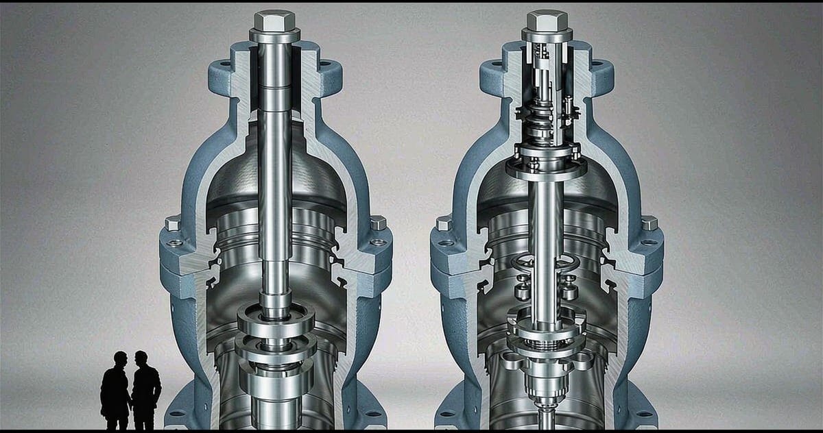
- Drilled-hole cages: a cylindrical cage pierced with many small holes, sometimes in multiple rings or stepped rows. Each hole is a restriction; groups of holes can be arranged so that not all stages engage at once, extending the range over which staging is effective. Robust, compact, and the workhorse solution for moderate-to-severe cavitation duties.
- Stacked disc trim: a package of precision plates, each laser-cut or etched with a flow pattern, stacked to form a tortuous multi-stage path. The per-stage geometry is designed independently — orifices, expanding sections, impingement zones — which gives designers fine control over where and how each portion of the drop is consumed. This is the highest-capability family and also the most sensitive to fluid cleanliness.
- Labyrinth trim: the continuous-channel cousin of stacked discs, with milled or formed channels winding through the flow path. Common in severe steam and letdown service where noise and vibration, not only liquid cavitation, drive the design.
Axial Versus Radial Flow Paths
Within these families, the direction the flow takes through the trim matters as much as the staging count:
- Axial flow paths carry the flow through the trim parallel to the valve axis, splitting it into many small parallel jets and recombining them gradually. Splitting flow into many small jets reduces the size of each disturbance and reduces the peak velocity per jet, which cuts both cavitation intensity and the aerodynamic/hydrodynamic noise radiated from downstream.
- Radial or combined paths route flow outward through cage windows or through disc stacks arranged around the centerline, trading some compactness for excellent distribution control and better handling of high flow rates.
Modern designs often combine both — a distribution stage, a throttling stage, a pressure-recovery stage — each optimized for its job. This is also why "number of stages" alone is a poor specification: two valves with the same stage count can behave very differently depending on the geometry within each stage.
The Noise Bonus
Although anti-cavitation trim is designed around liquid damage, the same physics that tames cavitation tames noise. Small parallel jets at reduced velocity radiate far less energy than a single large jet at full differential, and the staged recovery eliminates the shock cells and turbulence that dominate valve noise. In liquid service the benefit comes from avoiding cavitation itself; in gas service, labyrinth and multi-hole trims are selected for exactly this aerodynamic reason. When a noise specification is tight — near occupied areas, on high-pressure letdown — the noise prediction should be run jointly with the cavitation analysis, because the same trim families usually solve both and the stage count can be tuned to whichever constraint is more severe.
Determining the Stage Count and Drop Distribution
Stage count is not picked from a chart alone. A competent sizing analysis balances:
- The total available drop and the liquid's vapor-pressure margin at operating temperature.
- The flow range: a trim that stages perfectly at design flow may bypass its stages at low flow if the geometry is not range-compensated.
- Wear distribution: the drop should be allocated so no single stage carries a disproportionate share at any flow, since uneven allocation recreates localized cavitation.
This is where trim selection benefits from dialogue with the manufacturer's engineer — the analysis needs the actual flow envelope and pressure profile, not just the design point.
Cost Boundaries: When Anti-Cavitation Trim Is Overkill
Multi-stage trim costs real money and adds real restriction. It is the right answer when the valve sees continuous high differential on liquid service, when downstream equipment is cavitation-sensitive, or when noise limits are strict. It is the wrong answer when:
- The high-differential condition is brief and rare (a startup or blowdown event), where a simple orifice plate or restrictor series upstream can absorb the drop during the transient, or
- The drop can be shared with a static restriction — orifice plates in series remain a perfectly legitimate, low-cost solution for duties where the flow rate is stable and the valve only trims around it.
The engineering judgment is essentially economic: static devices consume drop cheaply but cannot adapt; dynamic trim adapts but costs more per stage.
Repair and Lifecycle
Multi-stage trims are replaceable by design — the cage or disc stack is a renewable element inside a standard body. Plan the lifecycle accordingly: specify renewable trim, keep the last test report on file, and inspect on a schedule driven by differential severity rather than calendar guesses. A valve that has been hammering itself for years with failed trim is usually recoverable with a trim change and a seat refinish — if the body and seat ring have not already been eaten past recovery.
An experienced manufacturer that produces the full valve range in-house — ball valves, control valves, gate valves, globe valves, check valves, strainers, knife gate valves, plug valves and butterfly valves — can support this review with cavitation analysis, trim selection, and renewable trim documentation for each high-differential position. Send your Valve Schedule or the operating pressure and flow envelope for each severe-duty valve to the manufacturer's applications team for a per-line proposal.