Aerodynamic Noise in Gas Service Valves: Prediction and
How aerodynamic noise forms in gas-handling valves, how IEC prediction methods frame the problem, and which mitigation routes — low-noise trim, diffusers, pipe treatment — actually work.
Aerodynamic Noise in Gas Service Valves: Prediction and Mitigation
Noise is not merely an annoyance in gas-handling plants — it is a symptom of violence inside the valve. The same flow structures that push sound pressure levels past occupational exposure limits also drive vibration, fatigue failures of trim and piping, and accelerated erosion. A control valve in high-pressure gas service that sounds like a jet engine is being consumed from the inside. Understanding where the noise comes from, how it is predicted, and which mitigation routes actually deliver is essential at the selection stage, because after installation the options narrow to what the pipe wall can absorb.
The Mechanism: Turbulence, Jets, and Shock Cells
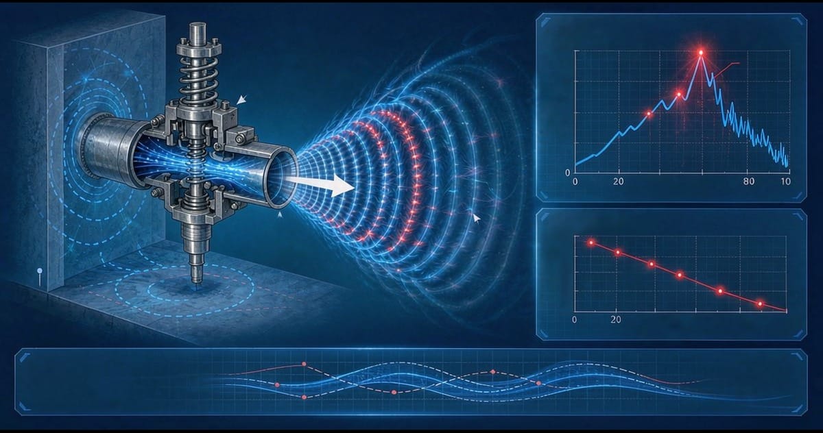
Aerodynamic noise begins as turbulent mixing. When gas accelerates through the valve's restriction, the resulting jet sheds vortices and produces broadband turbulence — this is the baseline sound, generally modest. The trouble starts as the pressure ratio across the valve rises.
- In subsonic operation, the jet's turbulent shear is the dominant source, and sound level grows steeply with jet velocity — roughly with a high power of velocity — which is why modest increases in pressure drop can produce dramatic increases in noise.- Once the pressure ratio crosses the critical threshold, the flow chokes and shocks form. The jet develops a train of shock cells — standing shock structures that interact with the turbulent shear layer. This interaction is an extremely efficient noise generator, and the character of the sound changes: broadband turbulence gains strong discrete tones — the screech of unstable shock cell feedback.
- Under highly choked, high-pressure-ratio conditions, shock-dominated noise dominates, and the acoustic power radiated can become a significant fraction of the flow's mechanical energy.
Two sensitivities follow: noise rises with pressure drop — the driver behind everything above — and with absolute flow rate. A valve passing a large flow through a modest pressure drop can be as loud as a small valve taking a brutal drop. That is why two valves in the same line can behave acoustically very differently, and why prediction must be done case by case, not by service category.
The Prediction Framework
The international prediction methods for control valve aerodynamic noise — IEC 60534-8-3 for the valve-internal mechanisms and IEC 60534-8-4 for alternative approaches built on the same physics — model the chain from flow energy to acoustic source to radiation. The framework decomposes the problem into stages: the energy of the jet and shock structures inside the valve, the efficiency with which that energy converts to sound depending on the flow regime and trim geometry, the transmission of that sound through the valve body and — usually dominant — the downstream pipe wall, and finally the external radiation to a defined point such as a meter from the pipe.
The concept that matters most to take from the framework is that the pipe is the loudspeaker. The internal sound field in the gas couples into the pipe wall, which radiates efficiently at certain frequencies. This has a practical consequence that surprises many engineers: pipe schedule affects noise. A heavier wall radiates less, and downstream piping treatment can be as effective as trim modification in some cases. The prediction methods account for it, so a calculated sound level is tied to the specified pipe construction — change the pipe, change the number.
Every valve manufacturer can produce a predicted sound level from these methods, but the prediction is only as good as the operating data behind it. A calculation at design flow says little about the valve's real duty, which often swings widely. Noise should be evaluated at the realistic operating cases, including turndown, not only at the nameplate condition.
Mitigation Route One: Low-Noise and Multistage Trim
The most direct attack is to change what happens inside the valve. Low-noise cage trim for globe-style control valves spreads the pressure drop and breaks the jet into many small streams.
- Multiple small orifices raise the frequency of the generated noise — smaller jets radiate at higher frequencies, where pipe radiation efficiency and human hearing sensitivity are less favorable — and reduce the per-jet acoustic energy.
- Multistage pressure reduction divides the total drop across successive restrictions, keeping each stage's pressure ratio below the level that forms strong shocks. This is the fundamental fix for high-pressure-ratio service: no single violent expansion, no shock-cell dominance.
- Combined designs — multistage with many small passages per stage — address both mechanisms and are the standard answer for severe gas letdown, including applications well above the range where a standard cage survives acoustically.
The trade-offs are real and belong in the selection discussion: low-noise trim costs more, holds less capacity for a given cage size because the flow passages are restrictive, and in dirty gas the small passages erode or plug faster than an open cage, so in erosive service the trim must be hardened and the noise solution must coexist with the wear solution.
Mitigation Route Two: Treat the Downstream Path
Where trim changes are impractical — an installed valve that must be replaced like-for-like, or a line where the noise budget is exceeded only slightly — the downstream path offers options.
- Orifice plates or diffuser plates downstream of the valve take an additional share of the pressure drop, lowering the ratio across the valve itself and reducing shock intensity. A diffuser engineered for the duty can take a large fraction of the drop and move the noise generation into a device built for it, at the price of permanent added line pressure drop and a device that must itself be checked for erosion.
- Acoustic insulation wrapped on the downstream pipe reduces radiated noise to the environment and is often the cheapest compliance measure, though it does nothing for the internal vibration and fatigue driving the problem.
- Heavier pipe schedule in the affected downstream section reduces radiation efficiency. Effective where new piping is being specified anyway, impractical as a retrofit.
- Silencers on the discharge of vent and flare valves — where the noise source is an atmospheric jet — are standard equipment and highly effective, provided they are sized for the actual flow and maintained against baffle fouling.
One caution: acoustic lagging treats the symptom heard by people, while multistage trim treats the source experienced by the equipment. A chronically noisy valve that has been lagged into acoustic compliance is still vibrating its trim and its piping, and fatigue failures will eventually surface somewhere lagging cannot hide.
Limits, Regulations, and the Selection-Stage Review
Plants work to noise limits in the occupied environment and to occupational exposure limits at the equipment — the specific numbers depend on jurisdiction and site standards. Either way, the limits are set per line and per case, which makes a noise review a routine part of valve selection in gas service: for each position, predicted level at the governing operating cases, compared against the site limit, with the mitigation chosen deliberately rather than discovered after startup.
The review is cheap when done at selection — a line item in the datasheet process — and expensive when done after commissioning. The inputs are already in the sizing case: flow, upstream and downstream pressure and temperature, gas properties, pipe schedule, and the site's acoustic criterion.
Verifying in the Field
Field measurement closes the loop. A survey with a sound level meter at the positions the prediction assumed — typically a stated distance from the pipe — confirms whether the installed reality matches the datasheet. Spectral measurements add diagnosis: broadband noise points to turbulence and choked flow, while discrete tones suggest shock screech or, sometimes, a structural resonance unrelated to the valve's aerodynamics. Measured-versus-predicted comparisons also calibrate future selections for that site, since pipe conditions and installation effects cause systematic differences from the idealized calculation.
Bringing the Acoustics into Selection
Noise in gas service is a selection-stage decision, not a maintenance-stage discovery. A manufacturer's applications team can run the prediction for each gas-handling position at your real operating cases, compare low-noise trim, multistage designs, and diffuser options against the site limits, and state the trade-offs in capacity and wear life rather than leaving them to be found on site. An experienced manufacturer that produces the full valve range in-house — ball valves, control valves, gate valves, globe valves, check valves, strainers, knife gate valves, plug valves and butterfly valves — can support this review with noise predictions and trim options for each position. Send your Valve Schedule or the key parameters for each gas service line to the manufacturer's applications team for a per-line proposal.