Articles Calculators Directory Catalog Knowledge Forum Projects Solutions
Sign In Register
Calculators › Floating Ball Valve › Stem Strength
Floating Ball Valve Suite · Q5-8/8

Floating Ball Valve Stem Strength

Verify multi-section stem torsional and bending stress: rectangular, annular, circular, keyway, and neck sections per the Valve Design Manual.

Open Calculator →
API Q41F 4" 300Lb · Valve Design Manual · PASS/FAIL Verdicts
Floating Ball Valve Stem Strength
Core Formula:
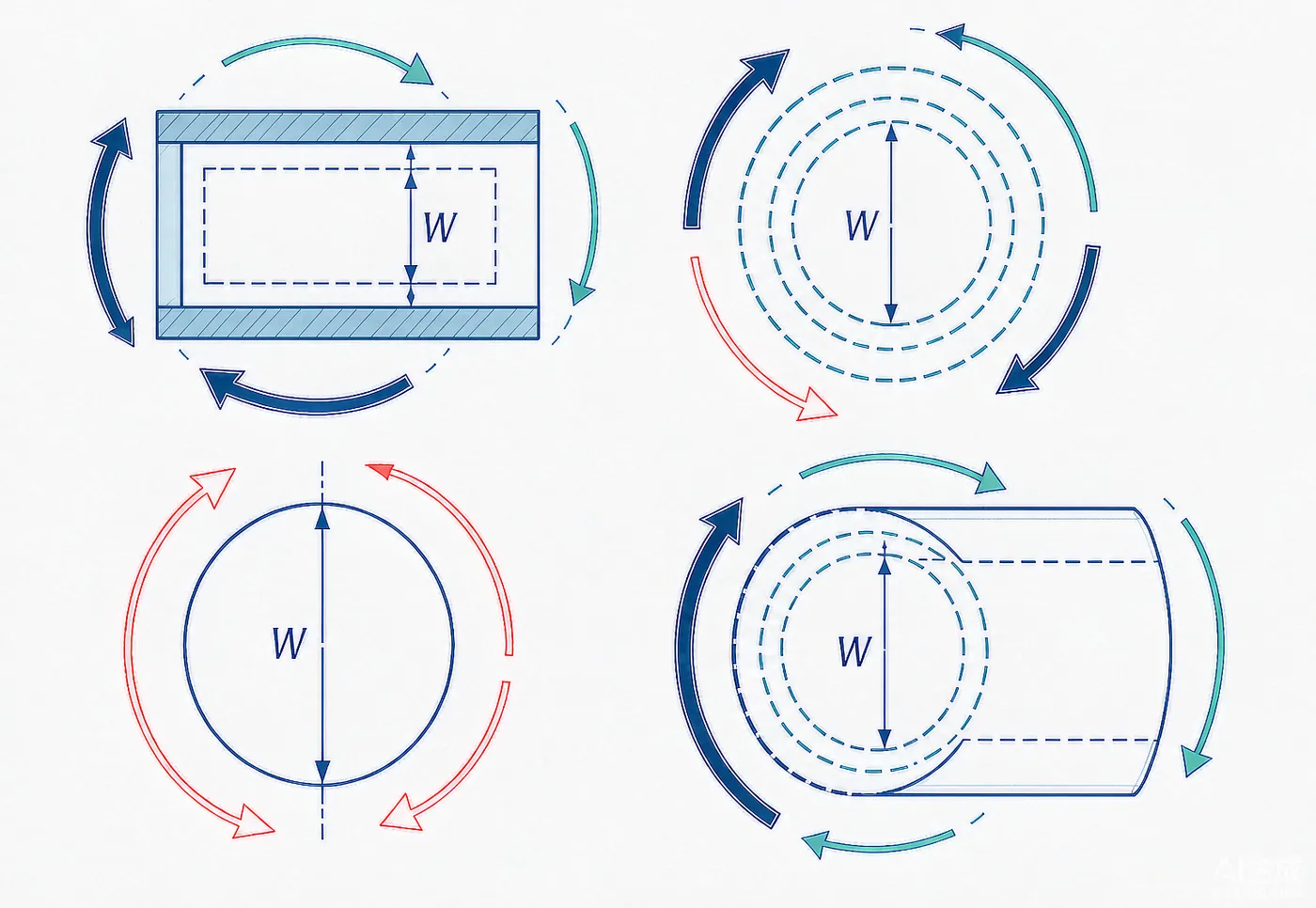
τN = Mm / W (section modulus)
σzy = Mm / (0.12·a²·h)
Check: σ ≤ [σ]

Why This Calculator

I-I Rectangular Section

Torsional stress at the rectangular stem drive section.

II-II Annular Section

Stress at the annular section with central bore.

III-III Circular Section

Plain circular section torsional stress check.

IV-IV Keyway Section

Stress concentration at the keyway drive section.

Neck Bending σzy

Bending stress at the stem neck transition, the critical section.

Part of Design Suite

Module 8 of 8 in the Floating Ball Valve design verification suite.

How It Works

Enter Stem Sections

Input dimensions for rectangular, annular, circular, and keyway sections.

Input Torque

Enter the operating torque Mm from the total torque module.

Compute Shear τN

Calculate torsional shear stress at each section.

Check Allowable

Verify τN and σzy against material allowable stress [σ].

Who Is It For

Valve Design Engineers | R&D Teams | QA/QC Engineers | Maintenance Planners

Key Highlights

Multi-SectionNeck BendingValve Design ManualAuto Calculation

Ready to Calculate?

Enter your design parameters and get instant verification results.

Open Calculator →